36+ automatic gain control block diagram
Assuming unity gain for. The capacitor C1 couples the audio signals from the output of the op-amp to the base of the PNP transistor.

Block Diagram Of Pwm Generation Circuit Circuit Design Positivity Circuit
It is important to notice that the VGA and the detector are the only nonlinear parts of the system.
. This variable capacitance appears across the first local oscillator coil and the frequency of this variable-frequency oscillator VFO is automatically kept from drifting with temperature line. Lal jani basha says. In his free time he writes on the blog talks over ham radio or builds.
45 dB analog variable gain range Reversible gain control sense Linear-in-dB gain control scaled 20 mVdB On-chip square-law detector Single-supply operation. Ad Templates Tools To Make Block Diagrams. The block diagram shown in figure 4a can represent such system.
If the gain control of only the sec-ond stage VGA is manipulated in the weak signal regime the signal level to the first stage VGAs amplifier in. This means that the receiver must have sufficient sensitivity to amplify fully very weak signals while also being capable of having its gain reduced by ACG action by a ratio of 10 5. Block diagrams consist of Blocks these represent.
November 10 2010 at 520 pm. 27 V to 55 V When a. This is because close-in targets are most likely to saturate the receiver.
Block Diagram Of Automatic Gain Control - PDF-BDOAGC13-3 12 BLOCK DIAGRAM OF AUTOMATIC GAIN CONTROL PDF-BDOAGC13-3 39 Page File Size 1696. Webb ESE 499 3 Block Diagrams In the introductory section we saw examples of block diagrams to represent systems eg. Circuit Diagram of Automatic Gain Control with Amplifier.
Beyond 50 miles stc has no. The stc voltage effect on receiver gain is usually limited to approximately 50 miles. The gain control inputs of the two de-vices.
Automatic control block summer. Functional Software Electrical etc. 13 comments on Automatic Gain Control Pre-Amplifier Circuit Diagram.
Modeling Lesson 5 Block diagrams Signal flow graphs Automatic Control by Meiling CHEN. Salil is an electronics enthusiast working on various RF and Microwave systems. Tanks for sending Reply.
The distortion contribution of each processing block must be a small fraction of the total allowed distortion budget 12.

Circuit Diagram Of Condenser Mircophone Coupler Circuit Diagram Circuit Circuit Design

Block Diagram Of Audio Mixer Circuit Circuit Circuit Design Audio
2

Audio Mixer With Multiple Controls Full Circuit Diagram Available Circuit Diagram Electronic Circuit Projects Audio Amplifier
Automatic Link Establishment System

Communication Receiver Block Diagram Block Diagram Diagram Communication

Measuring Power And Energy Consumption Using Pac1934 Monitor With Linux Developer Help
Automatic Link Establishment System
2
2
2
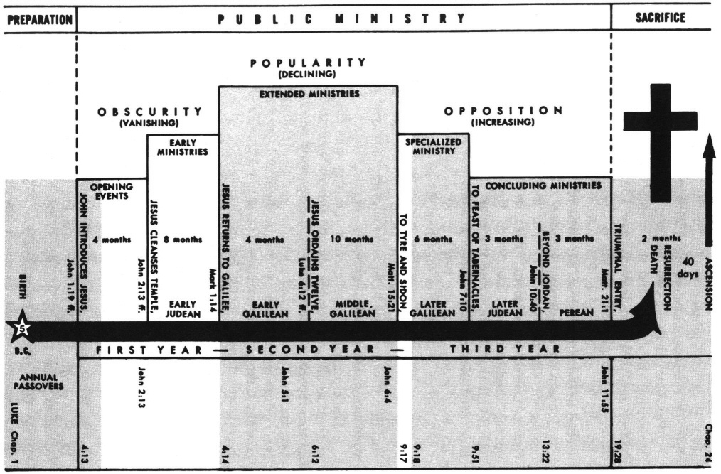
Luke 4 Commentary Precept Austin
2
Automatic Link Establishment System

Block Diagram Of Automatic Gain Control Circuit Agc Circuit Design Circuit Electronics Circuit

Circuit Diagram Of Automatic Gain Control With Microphone And Headset Connections Circuit Design Circuit Electronics Circuit
Determination And Use Of Feasible Operation Region In Flash Distillation Control Determination Y Uso De La Region Factible De Operation En El Control De Una Destilacion Flash Document Gale Academic Onefile